PC Automation Electrical CAD Software

Get Started Right Away!
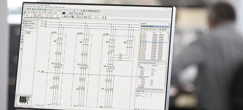
You have pretty much completed everything, even before you begin. In the electrical CAD software PCSCHEMATIC Automation, you merely have to drag partial diagrams and modules into your project. And then the documentation is ready. With electrical circuit diagrams, PLC diagrams and filled-in lists of any kind. But you can also draw the electrical diagrams yourself, if you wish to.
The Automation CAD software is created so that you just focus on the electrical design, and let the software handle the practical details.

With Automation, you achieve an efficiency which commands respect. Because you need only do things once:
- Once you have drawn a partial electrical circuit, you can drag it into each subsequent project
- Once you have set up partial or whole electrical projects, they can also be dragged in
- Thus you can create entire projects by merely dragging in partial drawings etc
This intelligent recycling makes you more efficient. At the same time, the electrical CAD allows you to create a uniform documentation that follows your company’s – or your customer’s – guidelines.
PC | Automation Variants
You don’t need to purchase the expencive variants of the software to get all the functionality you need!
Varient
Limitation
Automation Advanced
Unlimited
Automation Smart 40
Limited to 40 diagram/mechanical (except BOM, Lists etc) pages. Unlimited number of symbols.
Automation Smart 20
Limited to 20 diagram/mechanical (except BOM, Lists etc) pages. Unlimited number of symbols.
Automation Flex 350
Limited to 350 electrical symbols but unlimited number of pages.
Automation Flex 150
Limited to 150 electrical symbols but unlimited number of pages.
PC | Automation Feature List
Overview and navigation
- Project oriented: All parts of a project gathered as pages in a single file – including diagrams, mechanical pages, lists, tables of contents, chapter dividers etc.
- Enhanced Explorer window: For easy navigation between projects and project pages, and for finding symbols etc. in project pages
- Net navigator for easy navigation through electrical potentials
- Cross references are created and updated automatically for all types of components: Click and jump between the symbols for a component, or click in lists and jump directly to the component
- Object Lister for overview over all objects in the documentation – and for editing their attached texts/data. (Texts can also be edited by clicking on the individual texts in the project pages)
- Show available window: Easy access to all components with unused symbols/functions
Reference designations, templates, subdrawings, project generation …
- Creation and handling of reference designations at component, area, page and project level (function, location and product aspects) – according to IEC 81346, KKS or user defined standards
- Reference designations handled intelligently when changing, copying and merging pages and projects
- Project, page and list templates – just drag them into your projects
- Subdrawings / subdiagrams with attached article data – just drag them into your projects. Possible to select different sets of model data for each individual sub drawing
- Module and Model Based Drag’n Draw: Create full projects just by dragging in pages, sub drawings, lists and sub projects
- Automatic project generation via project definition file – e.g. via Excel (”Autodiagramming”)
- Automatic project generation based on selected options
- Panel router for automatic routing in conduits
- Mounting assistant for overview over and control of mounted components and wires
Databases, components and symbols
- 48 component manufacturer databases created designed specially for PCSCHEMATIC. All components have attached both electrical and mechanical symbols
- Component wizard for quick and effective creation of own components with attached symbols
- Unique timesaving database workflow: Symbol pickmenus for all multi-function components in the database – just click and place the symbols in the diagrams and article data are attached automatically
- Advanced copying: All symbols and their reference designations are renamed intelligently – e.g. when copying symbols and areas, or when inserting subdrawings, subprojects and projects. Attached article data are included when copying
- Rename symbols and Insert name at project level
- Automatic load of mechanical symbols for the components used – handled by the database
- Number of cable wires and colour codes controlled by the database
- Easy search for / editing of data for symbols and components
- Automatic documentation of symbol libraries and applied symbols in projects
- Comprehensive IEC 60617 symbol libraries
- Design your own symbols as well as Symbol generator for quick generation of simple symbols
- PCSCHEMATIC Database program Included for handling component data in e.g. Access
- ODBC and MDAC interface for communication with database systems
Drawing functions in the electrical CAD software
- Easy to get familiar with the program – and easy to create and maintain documentation
- Reuse existing documentation intelligently
- Automatic naming of all types of symbols
- Handling of subnames on symbols – including individual references
- Automatic naming and update of symbol names according to current path numbers possible
- Reference crosses or contact mirrors with cross references – click and jump to the individual symbols for the component
- Replace symbol function: On project or page level, and for individual symbols
- Handling of multi-layer terminals – electrically, mechanically and in lists
- Mounting correct drawing supported – with option to display in “dot” drawing mode
- Counting functions in numerous numbering systems
- Single-line and multi-line diagram features
- Lines are closed automatically when symbols are deleted
- Router: Automatic drawing of connecting lines – for instance when placing symbols
- Aligning, spacing and trimming functions
- Handling of jumper links and busbars
- Automatic wire numbering function
- Design check
- Watch motor control videos at the PCSCHEMATIC YouTube channel
Drawing headers, lists and import/export
- Automatic list update: Of tables of contents, parts lists (BOM), component lists, terminal lists, cable lists, connection lists, labels and PLC lists. Any of these lists can be defined freely by you
- Excel/XML/text files can be exported for all of the mentioned list types
- Export of wire numbers
- Drawing headers for any type of project page can be defined freely – and can be replaced on project level
- Automatic generation of graphical terminal, cable and connection plans
- Print labels via Excel or via e.g. CLIP PROJECT Marking or M-Print PRO
- Export of PDF files containing active links in the documentation
- Free PCSCHEMATIC Viewer
PLC features in the electrical CAD software
- PLC survey symbols
- Automatic PLC I/O addressing
- Automatically updated cross references between PLC symbols
- Import/export PLC I/O files to/from diagrams – e.g. via spreadsheet/Microsoft Excel
- Open for integration with PLC configuration tools – e.g. Simatic TIA configurator
- Watch PLC videos at the PCSCHEMATIC YouTube channel
House installation
- Import/export of DWG/DXF files (Member of Open Design Alliance)
- Drawing with elevation displayed in 2D or isometrically
- Unit drawings
- Pages for mechanical layouts and ground plan drawings as well as drawing in layers
- Measurement objects
- Design a panel, and the panel layout is generated automatically
- Single line diagrams are drawn automatically based on the panel design
- Document small switchboards and panels according to EN61439-1 and 3 concerning power dissipation calculation and more
- Watch electrical installations videos at the PCSCHEMATIC YouTube channel
Revision control, passwords, text translator, OLE objects and applications
- Revision control and revision clouds
- Password protection of projects
- Translation of texts on project pages
- Insert OLE objects and images
- OLE automation: Create your own scripts and applications for Automation (full documentation available)
For Netversions only
- Flexible sharing of net licenses and license borrowing
- Administrator control
Automation – Always Updated
More from PC | SCHEMATIC

PC | Cablemanager
Managing & Routing Cables

Standards Book
“Electrical documentation acc. to standards” – 3rd edition

Advanced Training
Also available as webinars

